
The humble patch bay is easily one of the most-used, and least-loved, pieces of equipment in the world of music-making. This is true, at least, on one side of the recording-studio glass. On the other, recording engineers feel a pleasant little flutter in their belly every time they patch a signal from somewhere to somewhere else. Oh, quelle convenience!
And there’s no reason you can’t benefit from that same convenience, too. As your own set-up continues to take shape (read: accumulates gear), so too do its possibilities expand. A patch bay is the key to unlocking them, whether you want to craft different signal chains for recording with or use your extensive collection of pedal effects and outboard gear to mix with.
In this article I'm going to go into detail on patch bays and how to set one up for your own studio.
Magnets Patch bays… how do they work?
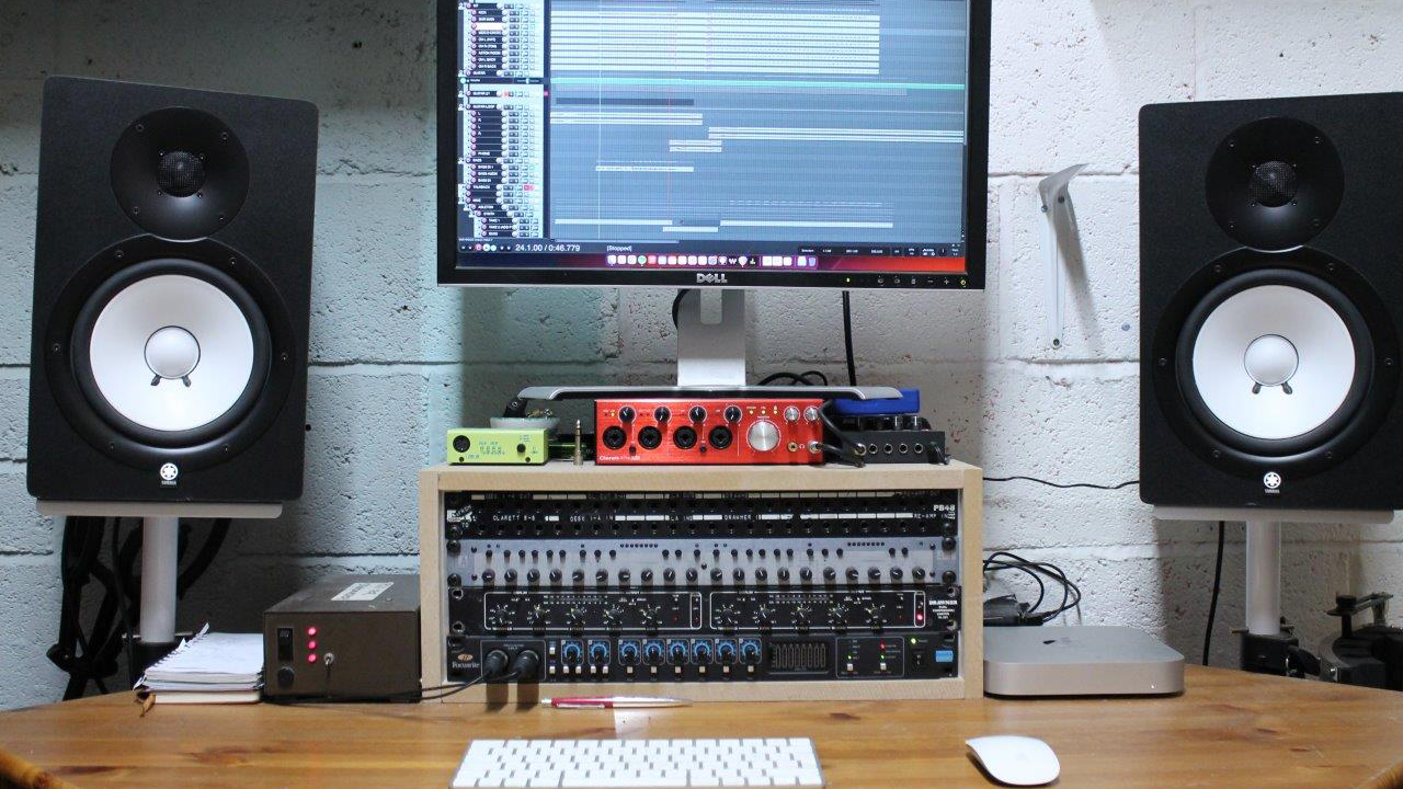
In patching something to somewhere else, you’re just dealing with ins and outs – exactly the same as with any other piece of audio equipment, only there’s an abstract slab of sockets between you and your stuff. Let’s use a guitar pedal to visualise things.
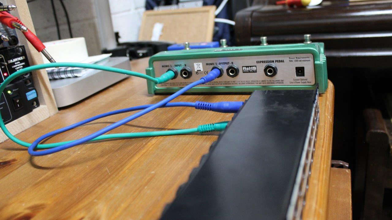
A signal is plugged into the bottom front socket, and the corresponding rear socket is connected to the input of this Line6 DL4 pedal. The DL4’s output is routed to the top rear socket of the same column, and accessed from the top front socket. From here, it can go wherever you’d like – including the bottom-front input of the next effect.
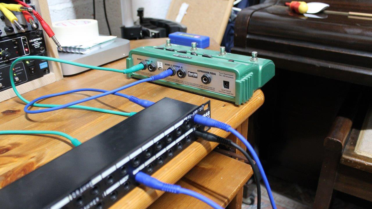
Some describe the flow of audio through a patch bay as being like a waterfall, but I like to start with stitching as an analogy. The needle and thread go in the bottom, back out through the top and then in through the bottom again.
How normal(led) is your patch bay?
Some patch bays stop here; each column is a new effect, and you effectively choose the order of effects with your patch cables at the front. These patch bays are called ‘un-normalled’ patch bays – which begs the question, ‘what is normal?’
Normalling refers to the internal connectivity of jacks in each column of a patch bay. In a normalled patch bay, the top-rear and bottom-rear jacks are internally connected, meaning signal automatically flows between them.
For normalled patch bays, this is always happening until you plug something in the front – at which point that internal connection is broken, and the signal diverted. This is useful where you have the output from a pre-amp coming in the top-rear jack, and the bottom-rear jack connected to the input of your audio interface; now you can patch in to that signal and send it elsewhere first, without unplugging a bunch of stuff.
Half-normalled patch bays also exist, wherein patching in at the top splits the signal instead of diverting it. However, plugging into the bottom front jack does break the connection, meaning whatever you’ve patched in will always take precedence (hence, half-normalled).
Now that you’ve got the skinny on patch bays, you’ve probably got some keen ideas on how to integrate one into your own rig. Let’s methodologise!
Step 1: draw up a plan
Every good setup starts with a plan. This isn’t just a way to feel productive before you start plugging stuff in; it’s a way to foolproof your patching ideas, finalise your set-up’s signal chain and give you a clear idea of what exactly you’ll need to realise your vision.
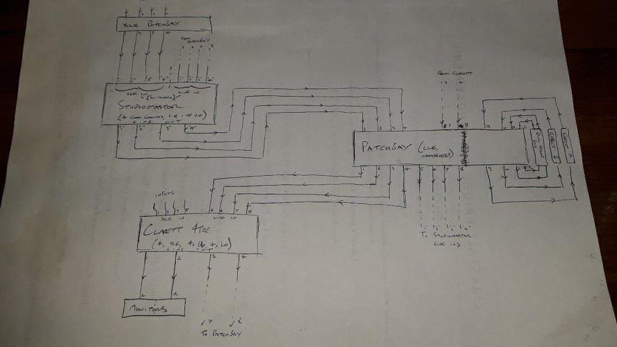
My plan involves a normalled patch bay; four channels of incoming audio are received from an analogue mixing desk, and normalled to the four rear inputs of a Focusrite Clarett 4Pre audio interface. The 4Pre’s line outs are also received in the patch bay, and normalled to the line inputs of the mixing desk.
This set-up enables the patching of audio to rack compression while recording, and the easy patching of outboard gear right back into the interface for re-recording. A stereo reamp box at the end of the bay enables the stepping-down of interface-borne audio to pedal-friendly levels, for even more versatility.
Step 2: get everything you need
For the most part, it’s cables. You need cables. And lots of them. Try cable looms for the rear of the patch bay, to make physically routing cables (and tracing signals) easier; for the front, you’ll want smaller 12” patch cables. For a TRS patch bay, make sure to buy TRS cables as opposed to TS for lower-noise audio!
Whether or not you have other rack effects to plug in, you should also buy a rack unit to house your patch bay. Patch bays are short and sometimes unhoused, so a rack can both protect your circuitry and make it easier to access.
Step 3: populate your rack
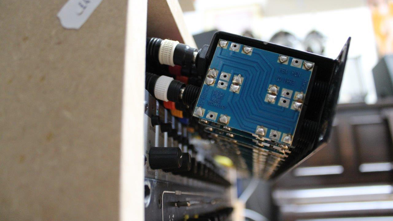
Using the four holes at the front of each rack effect panel, affix your rack equipment to the rails of your rack. The patch bay doesn’t go in yet, though, as you’ll want the space to make wiring easier. Speaking of which…
Step 4: wires, wires, wires
It’s wiring time! Start with the gear, as opposed to the patch bay, and start with anything multi-channel so as to keep your channels in the right order.
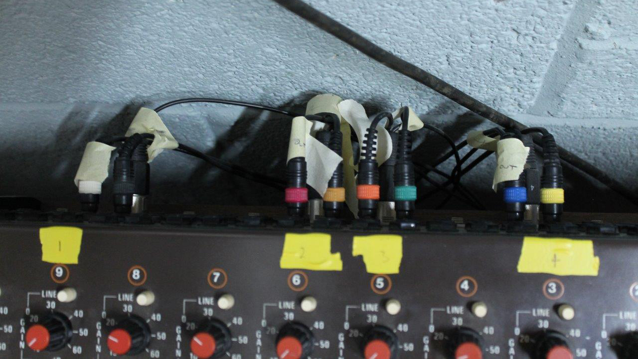
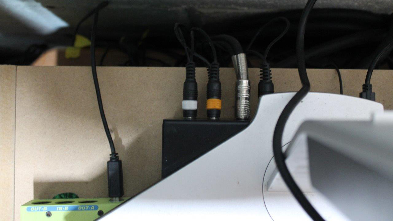
Labelling your cables, or noting their colour codes, is crucial to keeping track of cable runs. I've lost hours to forgetfulness in this regard; learn from my pain.
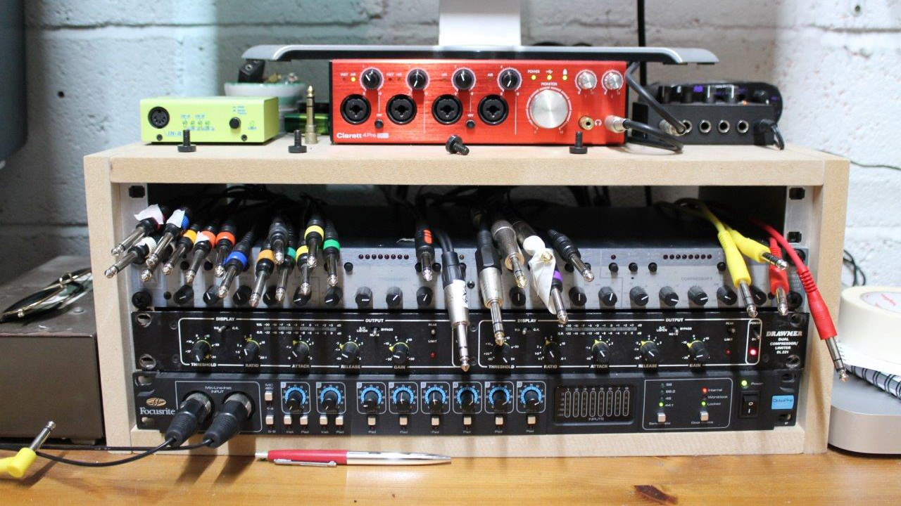
Here, all the cables are pulled through the gap where the patch bay will go. They are colour-coded and labelled for inputs and outputs, making plugging them in a simple matter of following the plan. Go methodically, left to right, and you won’t get lost (often).
Step 5: program your interface outputs
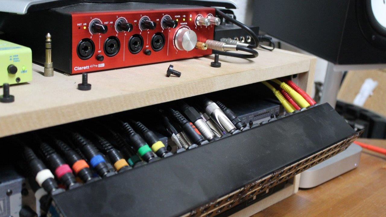
In order to use your audio interface outputs properly, you need to make sure they are routed correctly. Chances are they are routed as monitor outs, and so receive the same master-track info your speakers do. Fix this before you lose some hearing to a deafening feedback loop!
This step is actually sort of two steps, as you may have to work with both your interface’s proprietary software and your DAW. Whatever software it is, you should be able stop your line outs from automatically receiving stereo master information.
In your DAW, you can send audio out and back again any number of ways, including simply setting a send from a channel to the line out, and creating a new channel to receive the effected signal from an input elsewhere. You might benefit from creating a mix template in your DAW, with aux channels that automatically send to your line outs. This way, you can use your DAW’s send function, and buss whatever you like out to your patch bay. You could also create a virtual send and return path in your FX chain using an I/O plugin.
Step 6: profit
And that’s it! You’ve successfully installed a patch bay into your audio interface rig, and hopefully haven’t split any ears in the process. All that remains is to enjoy the near-endless possibilities your ins and outs afford you.


