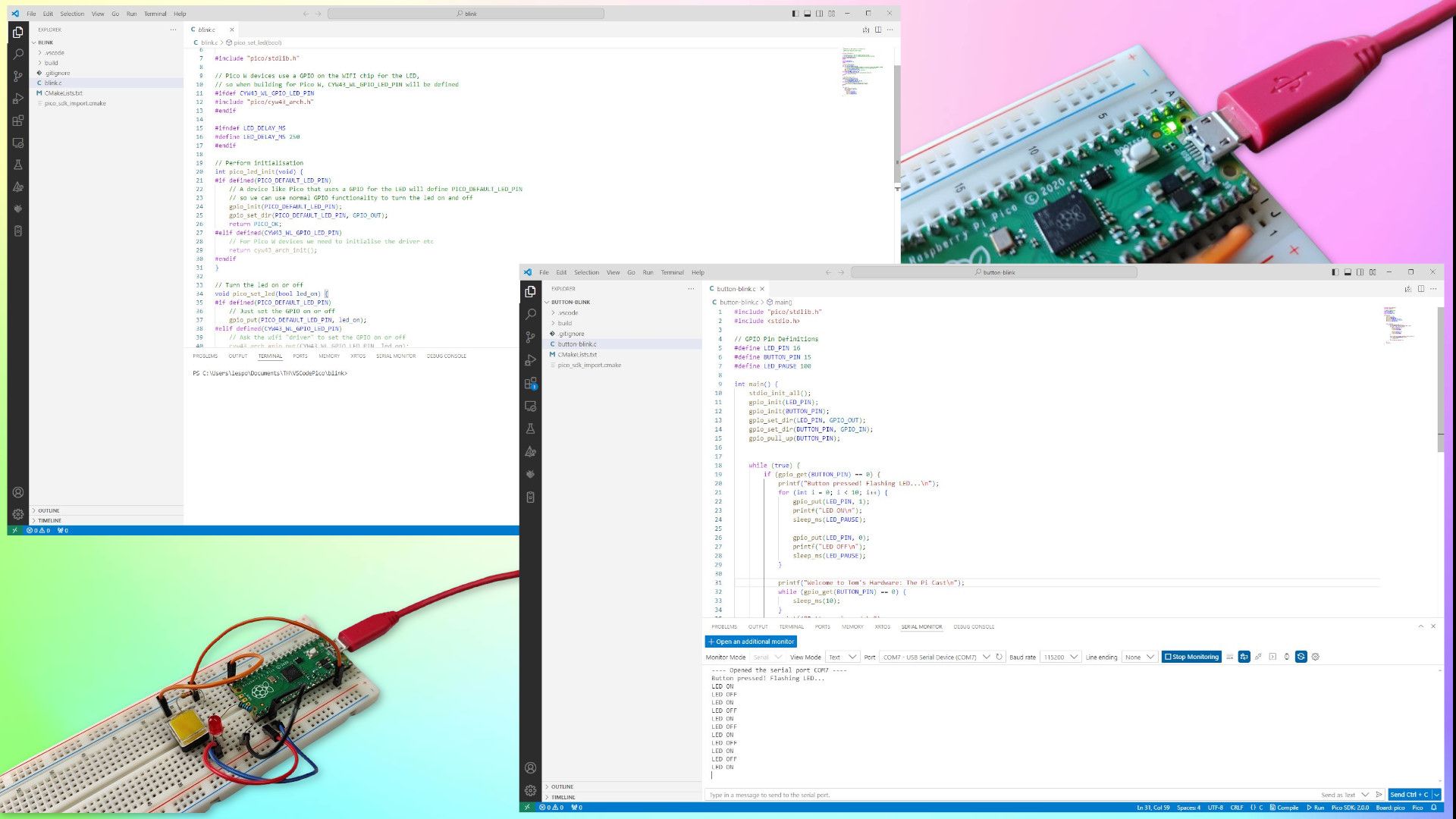
Every model of Raspberry Pi Pico, since its launch in 2021, has been programmable via a myriad of languages. For many, the go to languages being MicroPython and CircuitPython, but there are many users who opt for C/C++, Arduino or even TinyGo.
The “problem” with C-type languages for many new starters is the steep learning curve. There are a number of steps to take in order to get working code, something that Micro and Circuit Python abstract for the end user.
Raspberry Pi has sought to reduce the steep learning curve, and with its Raspberry Pi Pico extension for Microsoft’s Visual Studio Code, it has done just that. In this how to we will investigate how to get it running on a Windows PC, test out Raspberry Pi’s “blink” sketch to prove that our setup is working, and then write our own project.
This how to will work with every model of Raspberry Pi Pico, Raspberry Pi Pico W and the new Raspberry Pi Pico 2.
For this project you will need
- A Raspberry Pi Pico, Pico W or Pico 2
- A USB to micro USB cable (to flash the Pico)
- A breadboard
- An LED
- A button
- A 100 Ohm resistor (Brown-Black-Brown-Gold)
- A 10K Ohm resistor (Brown-Black-Orange-Gold)
- 5x Male to male jumper wires
- A computer running Windows 10 or 11
The first project that we will tackle is the “Hello World” of programming with electronics, making an LED blink. We do this to confirm that we understand the process, check that our hardware is working correctly and that we can write the necessary code to the Pico.
We start by getting our workspace setup for the task at hand.
1. Download and install Microsoft Visual Studio Code (VS Code) for Windows.
2. Follow the install and getting started process for VS Code. It will guide you through the basics of using VS Code.
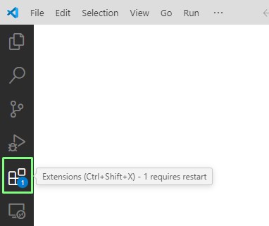
3. Click on Extensions.
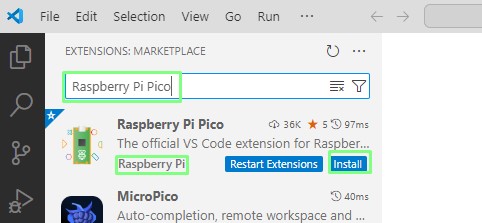
4. Search for Raspberry Pi Pico and click Install. Ensure that it is the extension provided by Raspberry Pi.
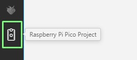
5. From the side bar, click on the Raspberry Pi Pico icon.
6. Click on New Project from Examples.
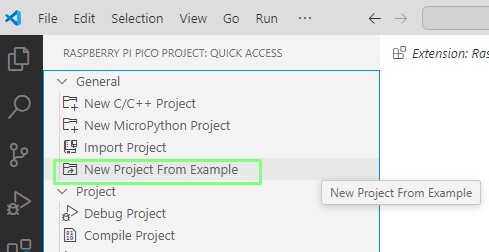
7. Click on the Name field and select the Blink example.
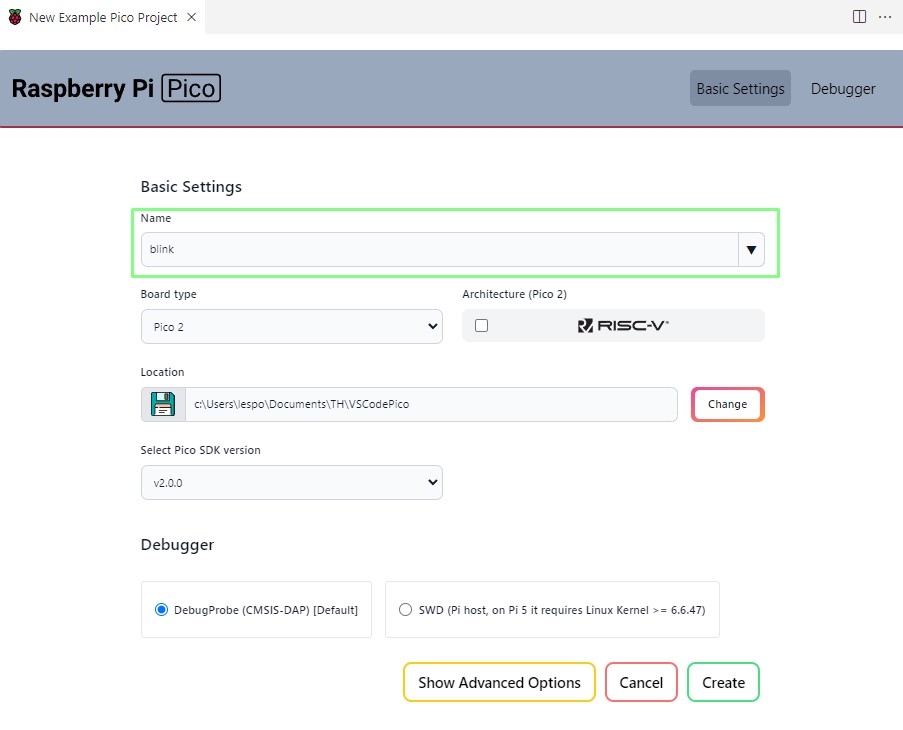
8. From Board Type, select your type of Pico. We’re using the original Pico for this project.
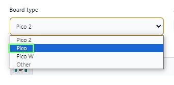
9. Set the location where the extension can create files for your project.

10. Click Create to build the project. The first time this is run, it may take a few minutes to complete. Be patient and answer any questions should they pop up.
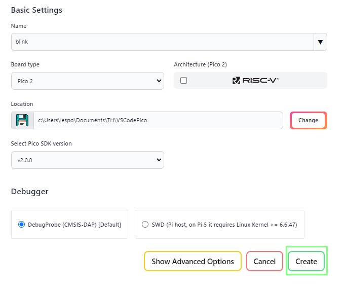
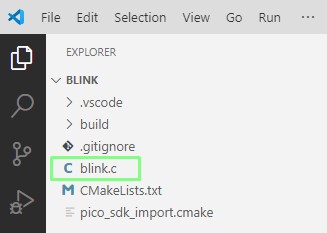
11. From the left sidebar open blink.c. This is the file that contains the code for this project.
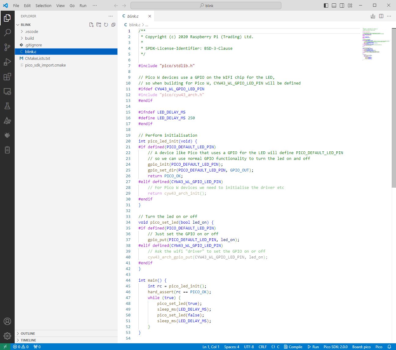
12. The example code opens in a new editor window. Do not make any changes, but take a look at the structure. It should be familiar to anyone who has used an Arduino before. We have includes, which are similar to Python’s import. We define variables to have certain data types. Conditionals (if, elseif and else) create a means to direct the flow of the code. Void (similar to Python functions) creates blocks of code that we can easily call. The main body of code is where we do all of the work.
13. Click on Compile to create a UF2 file containing the compiled project code.

14. Insert the USB cable into your computer, and while holding BOOTSEL on the Pico, insert the micro USB end into the Pico. The Pico will power up into a mode where it is awaiting new firmware.
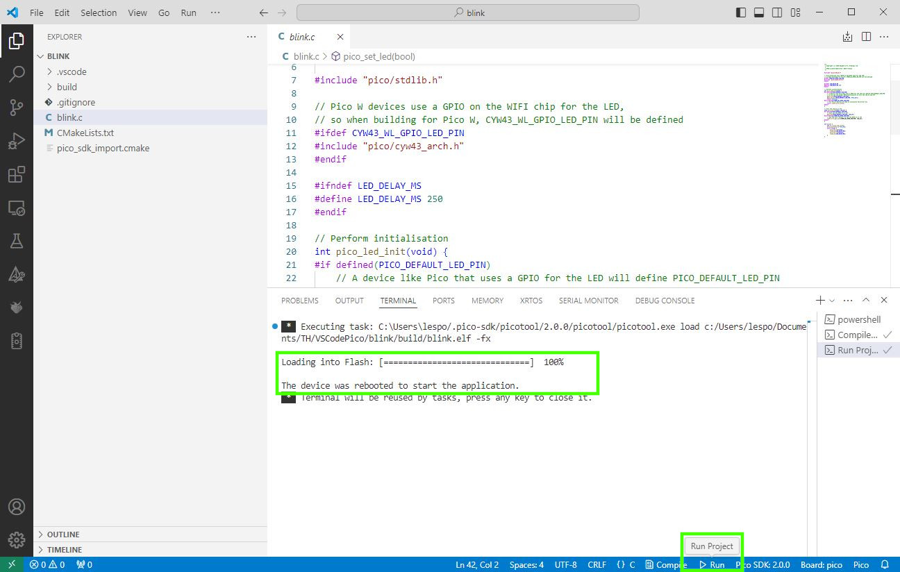
15. Click on Run and VS Code will find your Raspberry Pi Pico and flash the code to the board. When done, the output screen will say “The device was rebooted to start the application”.
16. Check that the onboard LED for your Raspberry Pi Pico is flashing. If so, you have correctly flashed code to the Pico. If not, unplug the Pico and reconnect to reboot.
Creating a push button LED project in C
Buoyed by our newtfound knowledge, let's create our own project. This time we have a push button which will cause an external LED to blink ten times. Each time the blink occurs, a message is printed to the serial console.
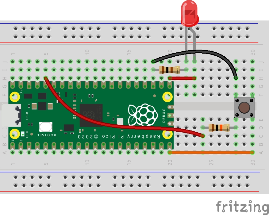
The circuit for this project is broken down into two areas, a push button (input) and an LED (output).
The push button connects to GPIO 15 on the Raspberry Pi Pico, any GND and to 3V3 via a 10K Ohm resistor which pulls the GPIO15 up.
The LED connects to GPIO 16 via a 100 Ohm resistor.
Build the circuit as per the diagram before moving onwards.
Now let's get back to writing code using VS Code.
1. From the side bar, click on the Raspberry Pi Pico icon.

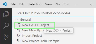
2. Select New C/C++ Project.
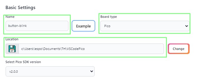
3. Call the project button-blink and set the board type to match your Pico. Keep the same Location as the previous project.
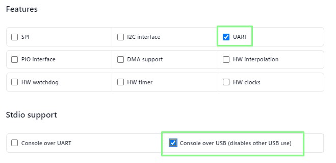
4. Under Features, tick UART (serial) under Stdio support tick Console over USB.
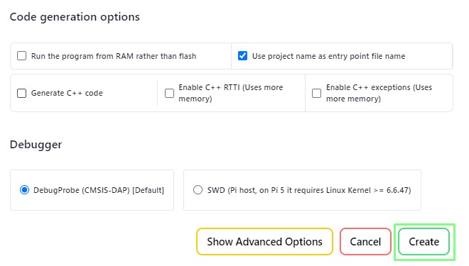
5. Click on Create to build the shell of the project.
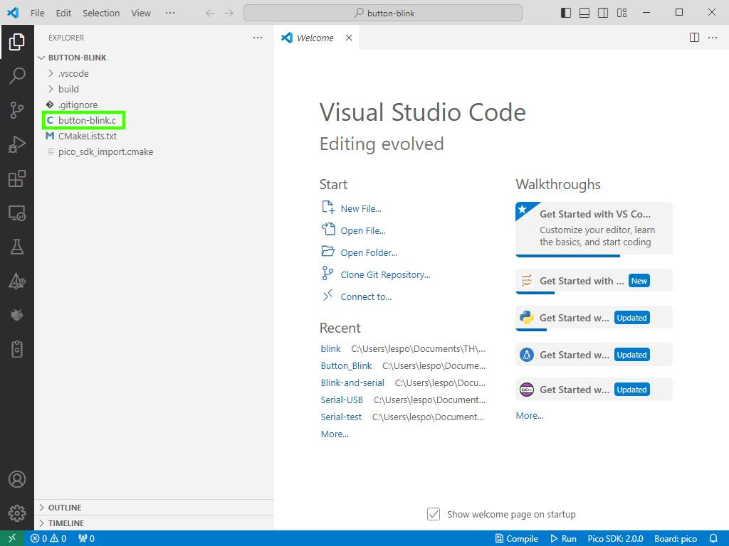
6. Click on button-blink.c to open the source code. Delete the boilerplate code.
7. We start the code by writing two includes for the C standard library (stdlib.h) and for basic serial communication (stdio.h).
#include "pico/stdlib.h"
#include
8. Create three variables to store the GPIO pin reference for the LED and button. Also create a variable for the pause between the LED turning on / off.
#define LED_PN 16
#define BUTTON_PIN 15
#define LED_PAUSE 100
9. Add these lines to initialize the standard I/O (for USB over UART) and for the LED and button.
int main() {
    stdio_init_all();
    gpio_init(LED_PIN);
    gpio_init(BUTTON_PIN);
10. Configure the LED as an output, and the button as an input.
    gpio_set_dir(LED_PIN, GPIO_OUT);
    gpio_set_dir(BUTTON_PIN, GPIO_IN);
11. Additionally set the button pin so that the internal resistor pulls the pin high. This means that when the button is pressed, the GND pin is connected to this pin, causing it to change state from high to low.
gpio_pull_up(BUTTON_PIN);12. Create a while True loop to run the contained code.
while (true) {13. Write a conditional test that will check if the button has been pressed and when done so, will trigger a message to the serial monitor. Remember the default state of the button is HIGH (1), when pressed, the button connects GPIO15 to GND, triggering the sequence to start.
        if (gpio_get(BUTTON_PIN) == 0) {
            printf("Button pressed! Flashing LED...\n");
14. Use a for loop to flash the LED ten times, printing a message to the serial monitor, before pausing for the duration stored in the LED_PAUSE variable (100ms).
            for (int i = 0; i < 10; i++) {
                gpio_put(LED_PIN, 1);
                printf("LED ON\n");
                sleep_ms(LED_PAUSE);
                gpio_put(LED_PIN, 0);
                printf("LED OFF\n");
                sleep_ms(LED_PAUSE);
            }
15. Print a message to the user, telling them to press the button., then add a while loop to check the pin state, and add a debounce time. Debounce removes unwanted button presses which can happen when the button is pressed slowly.
            printf("Press the button!\n");
            while (gpio_get(BUTTON_PIN) == 0) {
                // Debounce wait
                sleep_ms(10);
            }
16. Add a line to tell the user that the button has been released, and then end all of the loops to close the project code.
            printf("Button released.\n");
        }
    }
    return 0;
}
17. Click on Compile to create a UF2 file containing the compiled project code.
18. Insert the USB lead into your computer, and while holding BOOTSEL on the Pico, insert the micro USB end into the Pico. The Pico will power up into a mode where it is awaiting new firmware.
19. Click on Run and VS Code will find your Raspberry Pi Pico and flash the code to the board.
20. At the bottom of the screen, click on the Serial monitor.
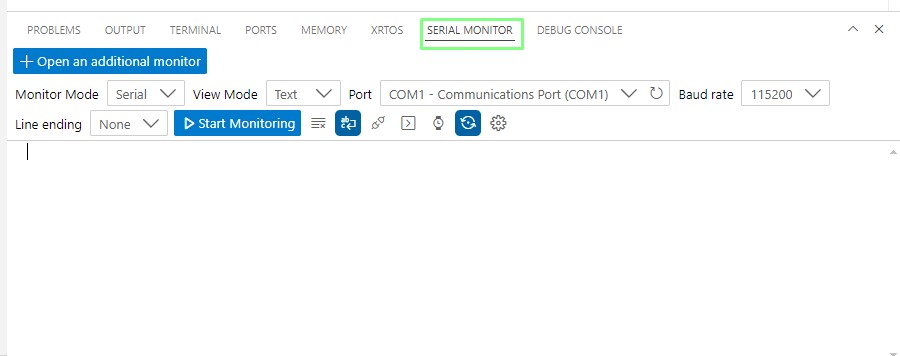
21. Via the dropdown, change the COM port to your Raspberry Pi Pico. This will differ depending on your setup. Check the COM ports in Windows’ Device Manager application.
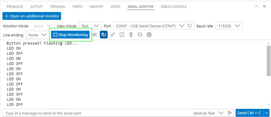
22. Click on Start Monitoring, to open the serial monitor.

23. On the breadboard, press the button to trigger the LED to blink. You will see the serial monitor output scrolling down the screen.
Complete Code Listing
#include "pico/stdlib.h"
#include

// GPIO Pin Definitions
#define LED_PIN 16
#define BUTTON_PIN 15
#define LED_PAUSE 100

int main() {
    stdio_init_all();
    gpio_init(LED_PIN);
    gpio_init(BUTTON_PIN);
    gpio_set_dir(LED_PIN, GPIO_OUT);
    gpio_set_dir(BUTTON_PIN, GPIO_IN);
    gpio_pull_up(BUTTON_PIN);

    while (true) {
        if (gpio_get(BUTTON_PIN) == 0) {
            printf("Button pressed! Flashing LED...\n");
            for (int i = 0; i < 10; i++) {
                gpio_put(LED_PIN, 1);
                printf("LED ON\n");
                sleep_ms(LED_PAUSE);

                gpio_put(LED_PIN, 0);
                printf("LED OFF\n");
                sleep_ms(LED_PAUSE);
            }

            printf("Press the button!\n");
            while (gpio_get(BUTTON_PIN) == 0) {
                sleep_ms(10);
            }
            printf("Button released.\n");
        }
    }
    return 0;
} 


